Using Less – Saving More | Reducing Costs – Systematically
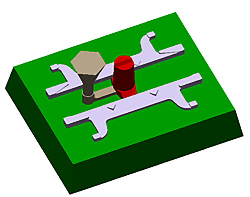
Usipe produced a 5.85 kg grate bar used in pallet cars for sintering using a no-bake sand casting process (Fig. 1). The flask- less mold weighed 139 kg and featured two cavities. The total casting weight was 11.7 kg. With the casting and feeder sys- tems, Usipe needed 21 kg of liquid metal to produce the part with a yield of 55.7 %. The sand-to-metal ratio was 6.6:1.
Using Less – the Best Recycling Method
In a competitive environment, the con- sumption of new sand becomes more and more important: A reduction in new sand use will also lead to a reduction in cost. To reduce consumption, foundries recycle large quantities of used sand [1]. The used sand, however, must be intensively cleaned and prepared for re-use. This is the only way to avoid defects caused by residual impurities or residual binders [2]. However, the processing costs increase significantly for this very reason.
The engineers at Usipe thought it would be better to not use the sand at all. This would allow them to reduce both pro- duction and sand preparation costs.
The foundrymen knew the MAGMA APPROACH. And used it. Their goal was to systematically reduce the amount of mold material in the casting process and thus improve the sand-to-metal ratio, ultimately resulting in reduced manufacturing costs.
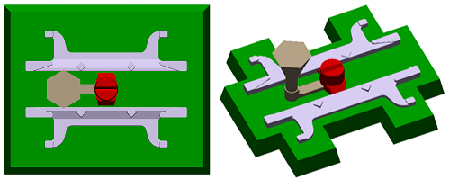
The engineers at Usipe planned to adjust the wall thicknesses of the mold (Fig. 2) to reduce sand con- sumption. They also wanted to decrease the size of the feeder – without compro- mising the dimensional accuracy and quality of the cast parts. The degrees of freedom were clear: feeder dimensions and outer contour of the mold.
The challenges here were: If the engineers change the wall thickness of the mold, the thermal boundary conditions, the mechanical properties and the rigidi- ty of the mold will all change. The wall thickness also influences the tempera- ture history in the mold material and, thus, the binder degradation. If the bind- er degrades too quickly, this could lead to casting defects, and the mold might break during filling before a solidified shell has formed.
Therefore, Usipe decided to carry out indi- vidual simulations with different mold ge- ometries. First, the experts evaluated the established process to understand which parts of the mold could be removed.
As shown in Figure 3, they planned to remove all four corners and two large ar- eas along the vertical axis of symmetry (Fig. 3a) while reducing the height of both mold halves (Fig. 3b). They also re- duced the feeder size: The foundrymen cut the feeder height in half, which saved 1.8 kg of molten metal per casting – pro- vided that no hot spots formed.
Less of Everything – With the Same Result?
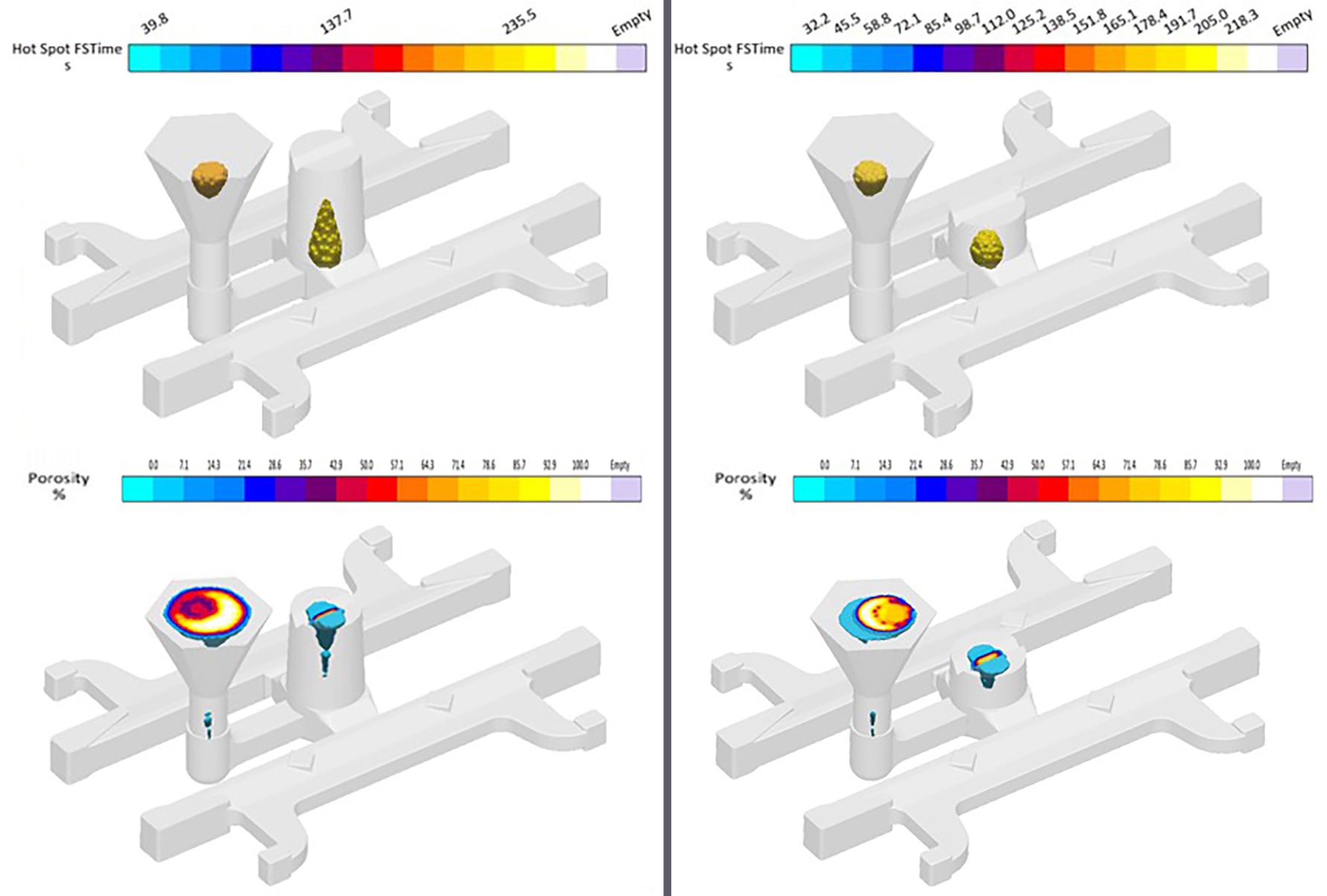
To test the new mold design and rule out casting defects, the engineers simulated filling and solidification. They found out that the reduced feeder did not compro- mise the casting quality. Both hot spots and porosity shifted slightly, but were still confined to the feeder (Fig. 4, left: original mold; right: new mold).
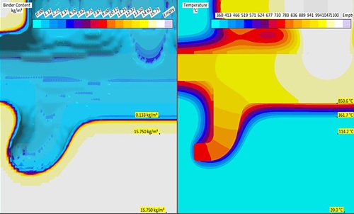
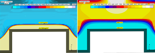
The modified mold design had thin wall sections. If the binder degradation in these areas was too pronounced, the stability of the mold would be reduced, formed in the casting by then. The ex- perts examined these areas more close- ly and compared the simulation results with those of the original mold 10 min- utes after filling was complete, that is, at the time when a stable solidified shell should have formed.
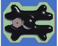
In the original design, the binder degra- dation reached about 8.7 mm ±2 mm into the mold. In this area, the binder content dropped to 0.133 kg/m³ (Fig. 5a). With the adjusted mold, adjacent areas heated up more, so that the binder deg- radation reached up to a depth of 16mm not decrease as much in these areas (1.317 kg/m³, Fig. 5b). Under these con- ditions, the engineers did not expect major casting defects to occur.
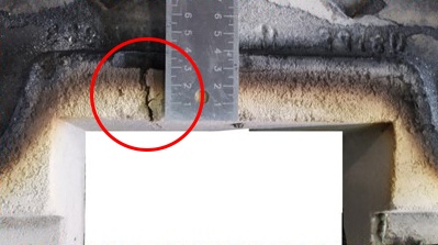
Therefore, Usipe proceeded and pro- duced a prototype. During the test, how- ever, a crack formed in the bottom half of the sand mold (Fig. 6). This crack could potentially lead to a significant in- crease in the scrap rate.
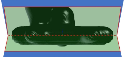
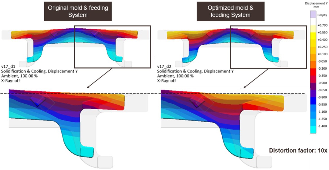
To check whether this defect affected the quality of the casting and whether adjustments to the mold were necessary, the foundrymen used MAGMAstress to cal- culate stress distributions and deforma- tions of the casting. The results revealed a solidification-related distortion along the main axis of the casting, which caused the crack in the mold half (Fig. 7). Although the deformation damaged the mold, the distortion of the casting was within the tol- erance range: Usipe was thus able to pro- duce the part – without increasing scrap.
Less of Everything – More Competitiveness!
Consistently applying the MAGMA APPROACH helped Usipe’s engineers to define goals and find solutions at an early stage. This enabled them to efficiently identify and take the right measures to both prevent defects and meet quality criteria – achieving all that with fewer resources.
Working methodologically, the experts reached all their goals: They improved the sand-to-metal ratio to 4.7:1 and reduced the required amount of liquid metal from 21 kg to 19.2 kg. As a result, they man- aged to reduce sand and melt consump- tion by 30 % and 8.5 %, respectively. With an annual production volume of 5000 parts, Usipe thus saves 9 t of metal and 240 t of sand. They increased the yield to
60.9 %, which resulted in direct cost sav- ings. In addition, indirect costs were also reduced. Usipe had to heat less liquid metal and prepare less sand for re-use, thus saving money along the entire process chain.
About USIPE:

